INTRODUCING THE DATCUBE 82
POWER FOR THE FUTURE · AUSTIN, TEXAS · 1982
WORKSTATION EMULATOR
Initializing…
USER: Dr. Eva Magnus // CHIEF RESEARCHER DATE: [REDACTED] 2082
To the original Dat Sys engineering team: Thank you. It is the year 2082, and the world is on the brink. While modern systems failed to sequence the XT9007 antigen due to modern quantum-locking countermeasures, your legacy architecture—specifically the raw DMA bypass of the QC-1's M3D coprocessor—allowed me to build the Antibody Designer. The DatCube 82 is currently the only machine keeping this pandemic at bay. But I cannot do this alone. We need more operators to run the simulations. Join the fight.
> INITIALIZE ANTIGEN BLASTER PROTOCOL
USER: Dr. Aris Thorne // APPLIED PHYSICS DATE: NOV 14, 1984
We blew our entire departmental budget on this machine ($176,500!), but the DCIS-2 instruction set is unparalleled. The copper-bar HBL interrupts are a nice party trick, but the real magic is the Quantum RAM bandwidth. Worth every single penny.
USER: [CLASSIFIED] // DEPT. OF ENERGY DATE: MAR 02, 1987
The mesh rendering capabilities completely exceed our current fluid dynamics simulation needs. Build quality is exceptional. We are, however, still trying to decipher the proprietary DNS-based serial networking protocol.
Technical Specifications
Built for Research.
Born to Compute.
CPU
Processor
QC-1 Quantum Core 1
Custom 16-bit CISC processor running at 8.008 MHz. 8 general-purpose 16-bit registers (R0–R5, MX, SP). Hardware-accelerated multiply/divide. Full IRQ support with 8 priority vectors.
ISA
Instruction Set
DCIS-2 · 100 Mnemonics
DatCube Instruction Set version 2. 16-bit word encoding, 1–2 words per instruction. 4-bit primary opcode; every instruction carries a 3-bit condition prefix (AL/EQ/NE/CF/CC/MI/VS/LT) for zero-overhead conditional execution. 100 mnemonics spanning ALU, FPU (48-bit), M3D mesh rendering, and Audio DSP. Four virtual segment registers (DS, ES, XS, CS) with 8-bit page mapping.
RAM
Memory
4 × 64 KB Internal
+ 1 MB Expansion
4 internal "Quantum RAM" segments (SEG 0–3). Expansion slot provides up to 16 × 64 KB pages (SEG 4–7), page-mapped at runtime via I/O registers. DMA controller for segment-to-segment block transfers.
VID
Video
512 × 288 · 60 Hz
5-Layer Compositor
16:9 progressive scan. Layer 0: 24-bit RGB copper-bar fill (per-scanline HBL IRQ). Layers 1–4: freely compositable text or pixel layers, 1/2/4/8bpp palette, Z-order assignable, split-screen via row skip/count.
M3D
3D Coprocessor
M3D · DMA Triangle Fill
Hardware vertex mesh renderer. Vertex format: 3 × s16 (X/Y/Z). Face format: 3 × u16 indices + u8 palette. Modes: wireframe, flat-shaded, textured, sprite. Accessed via MMSH / MLDV / MLDM / MREND instructions. IRQ5 on completion.
SND
Sound DSP
4-Channel + PCM DMA
5 synthesis waveforms (SQR, SAW, TRI, SIN, NOI) plus custom PCM. Full ADSR envelope per channel. PCM streaming via DMA: once, loop, or ping-pong. Configured via SWAV / SPCH / SEFF / SPLY / SSTP instructions and I/O ports 0x30–0x39.
100 Mnemonics
256 KB Internal + 768 KB Expansion RAM
5 Video Layers
4 Sound Channels
8 IRQ Vectors
100 Mnemonics.
Zero Compromises.

System & Control

HLT0x00Halt processor; set H flag
NOP0x01No operation; optional 8-bit steganographic payload
INT0x02Software interrupt — dispatch to vector n (0–15)
EI0x03Enable interrupts (set I flag)
DI0x04Disable interrupts (clear I flag)
STSG0x05Set segment page (0–7) for DS/ES/XS/CS
STSGR0x06Set segment page (0–255) for DS/ES/XS/CS from register

ALU — Register-Register

ADD0x10Rd = Rd + Rs (sets C, V, N, Z)
SUB0x11Rd = Rd − Rs (sets C, V, N, Z)
MUL0x12Rd:Rd+1 = Rd × Rs (32-bit product)
DIV0x13Rd = Rd ÷ Rs; NMI on divide-by-zero
AND0x14Rd = Rd AND Rs (sets N, Z)
OR0x15Rd = Rd OR Rs (sets N, Z)
XOR0x16Rd = Rd XOR Rs (sets N, Z)
CMP0x17Set flags for Rd − Rs; no store

Register Operations

MOV0x20Rd = Rs
NOT0x21Rd = ~Rs (Rs defaults to Rd)
NEG0x22Rd = −Rs (two's complement; Rs defaults to Rd)
INC0x23Rd = Rs + 1 (Rs defaults to Rd)
DEC0x24Rd = Rs − 1 (Rs defaults to Rd)
SHL0x25Logical shift left; Rd = Rs ≪ n (register or imm 0–15)
ASL0x26Arithmetic shift left — alias for SHL (identical encoding)
SHR0x27Logical shift right; Rd = Rs ≫ n (register or imm 0–15)
ASR0x28Arithmetic shift right, sign-preserving; Rd = Rd ≫ Rs
CLZ0x29Rd = count of leading zeros in Rs
XCHG0x2ASwap Rd ↔ Rs

Load — Register-Indirect

LDR0x30Rd = MEM_WORD[SEG:Rs] (.INC suffix auto-increments Rs)
LDRB0x31Rd = zero_ext(MEM_BYTE[SEG:Rs]) (.INC suffix valid)
LDSB0x32A = sign_ext(MEM_BYTE[SEG:Rs]) (destination always A)

Store — Register-Indirect

STR0x38MEM_WORD[SEG:Rs] = Rd (.INC suffix auto-increments Rs)
STRB0x39MEM_BYTE[SEG:Rs] = Rd[7:0] (.INC suffix valid)

Block Transfer

RPW0x3ARepeat copy/fill words; SEG:Rd ← DS:Rs, C words (C < 0 = fill |C| words)
RPB0x3BRepeat copy/fill bytes; SEG:Rd ← DS:Rs, C bytes (C < 0 = fill |C| bytes)

Immediate Arithmetic & Logic ★

ADDI0x40Rd = Rs + imm16 (Rs defaults to Rd)
SUBI0x41Rd = Rs − imm16 (Rs defaults to Rd)
CMPI0x42Set flags for Rs − imm16; no store
ANDI0x43Rd = Rd AND imm16
ORI0x44Rd = Rd OR imm16
XORI0x45Rd = Rd XOR imm16
SHLI0x46A = A ≪ count (count 0–15; always register A)
SHRI0x47A = A ≫ count (count 0–15; logical; always register A)

Load — Absolute / Indexed

LDI ★0x50Rd = imm16 (load 16-bit immediate, 2-word)
LDIS0x51Rd = imm7 (1-word; Rd ∈ {A–D}; immediate 0–127)
LDA ★0x52Rd = MEM_WORD[[sg,] addr16] (load word, absolute)
LDAB ★0x53Rd = zero_ext(MEM_BYTE[[sg,] addr16]) (load byte, absolute)
LDX ★0x54Rd = MEM_WORD[Rs + offset16] (load word, register+offset)

Store — Absolute / Indexed

STA ★0x58MEM_WORD[[sg,] addr16] = Rs (store word, absolute)
STAB ★0x59MEM_BYTE[[sg,] addr16] = Rs[7:0] (store byte, absolute)
STX ★0x5AMEM_WORD[Rd + offset16] = Rs (store word, register+offset)
STXB ★0x5BMEM_BYTE[Rd + offset16] = Rs[7:0] (store byte, register+offset)

Stack

PUSH0x60Push Rd; optional flag also pushes PC and/or CS
POP0x61Pop word from stack into Rd
PUSHA0x62Push all 8 registers + SR onto stack
POPA0x63Pop all 8 registers + SR from stack
RET0x64Return from subroutine (pop PC)
RTI0x65Return from interrupt (restore SR, PC, CS)
FRET0x66Far return — restore CS and PC from stack
MRES0x67Multi-register restore (pop subroutine frame)
MWAIT0x68Stall until M3D coprocessor completion

Branch & Flow

JR0x70Relative jump ±256 words from PC (1-word; 3-bit condition prefix)
JSRR0x71Relative call ±256 words (1-word; push PC, then JR)
JMP ★0x72Absolute jump to addr16 (unconditional or condition-prefixed)
FJMP ★0x73Far jump — set CS = sg, PC = addr16
JSR ★0x74Call subroutine — push PC, jump to addr16
FJSR ★0x75Far call — push CS+PC, set CS = sg, PC = addr16
JMPR ★0x76Register-indirect far jump: CS = Rs, PC = Rd + offset16
JMPX ★0x77Indexed jump via table; entry = [sg:addr + Ri × 4]

I/O

IN ★0x80Rd = I/O port[port16] (read 16-bit I/O port)
OUT ★0x81I/O port[port16] = Rs (write 16-bit I/O port)

FPU — Memory Ops

FLD0x90FACC = MEM_48[Rs] (load 48-bit float from DS:Rs)
FST0x91MEM_48[Rs] = FACC (store 48-bit float to DS:Rs)
FADD0x92FACC = FACC + MEM_48[Rs]
FSUB0x93FACC = FACC − MEM_48[Rs]
FMUL0x94FACC = FACC × MEM_48[Rs]
FDIV0x95FACC = FACC ÷ MEM_48[Rs]
FCMP0x96Set FPU flags: FACC − MEM_48[Rs] (no store)

FPU — Internal Ops

FXCH0x98Swap FACC ↔ FOP
FADDO0x99FACC = FACC + FOP
FSUBO0x9AFACC = FACC − FOP
FMULO0x9BFACC = FACC × FOP
FDIVO0x9CFACC = FACC ÷ FOP

M3D Coprocessor ★

GMUL0xA0GPU matrix multiply; mode selects transform pipeline
MTEX0xA1Set texture memory pointer (segment + address)
MMSH0xA2Set mesh array pointer (segment + address)
MREND0xA3Render n triangles (0=wire, 1=flat, 2=tex, 3=sprite); IRQ5 on done
MLDM0xA4DMA-load 4×4 transform matrix from memory
MLDV0xA5Set vertex array pointer (segment + address)
MCTRL0xA6M3D control register write (param, value16)
VCFG0xA7GPU layer compositor control word

Sound Channel Control

SPLY0xB0Play channel ch (0–7)
SSTP0xB1Stop channel ch immediately
SCFG0xB2Load channel config from register Rs

Sound DSP ★

SWAV0xC0Set waveform: 0=SQR 1=SAW 2=TRI 3=SIN 4=NOI 5=CUST
SPCH0xC1Set channel frequency in Hz
SEFF0xC2Set ADSR envelope word (att|dec | sus|rel)
SCUST0xC3Set custom PCM buffer pointer (ch, sg, addr16)
SDUR0xC4Set playback duration in milliseconds
SVOL0xC5Set channel volume and stereo panning
SPCM0xC6Stream PCM audio from segment:address (once / loop / ping-pong)
SAUX0xC7Auxiliary DSP parameter write
Dat Sys Computer Inc.
Austin, Texas · 1976–1985
1976
Founded in a Garage on Barton Hills Drive
Three electrical engineers — Harold "Hal" Datten, Roy Systemski, and Evelyn Morse — pooled $18,000 in savings to found Dat Sys Data Systems in a rented garage in south Austin. Their initial focus was custom memory controllers for university mainframe systems. Hal had previously worked at Texas Instruments; Roy and Evelyn met at UT Austin's Electrical Engineering department.
1979
The QC-1 Chip: A Secret Project Begins
After landing a contract with the Southwest Research Institute to build a custom data-acquisition workstation, the team began secretly developing their own 16-bit processor — the QC-1, or "Quantum Core 1" (clocked at 8.008 MHz). The name was partly ironic: the chip had nothing to do with quantum physics. Hal simply liked the sound of it. Tape-out was completed in late 1979 using a process node licensed from Motorola.
1981
DCIS-2 ISA Finalised; First Prototype Boot
After eighteen months of revision, the DatCube Instruction Set v2 was frozen. The team discarded an earlier RISC-influenced design after benchmarking showed that the denser variable-length encoding of DCIS-2 gave better real-world throughput on their target workloads — scientific visualisation and signal processing. On April 3rd, 1981, the first QC-1 prototype board successfully booted to a command prompt. Roy reportedly cried.
1982
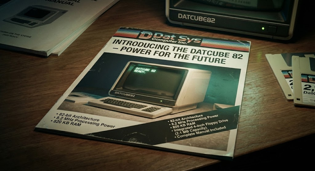
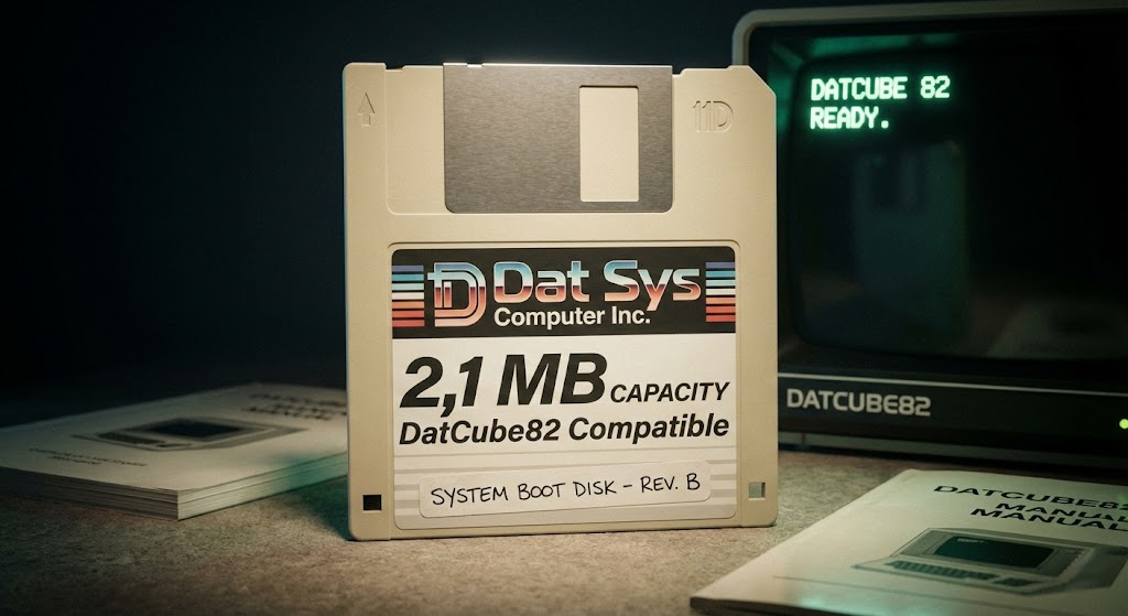
The DatCube 82 Ships to Research Institutions
Priced at $176,500 USD (roughly $590,000 in 2025 dollars), the DatCube 82 was never intended for the consumer market. Units shipped exclusively to research institutions, government laboratories, and select university departments. Fewer than 200 units were ever built. The machine featured the QC-1 processor, 1 MB of internal/external RAM, a custom 5-layer video compositor capable of 512×288 resolution at 60 Hz, a 3D mesh coprocessor, and a 4-channel sound DSP — a combination that would not appear in any consumer machine for nearly a decade.
1984
The DC-84 Project and the IBM Pivot
Plans for a follow-up machine — the DC-84, featuring a revised QC-2 processor at 10 MHz and 2 MB of base RAM — were shelved when Dat Sys Computer Inc. received a lucrative offer from IBM to license the DMA architecture underlying the M3D coprocessor for use in high-end IBM workstations. The company quietly pivoted to semiconductor IP licensing. The Austin office was closed; Evelyn Morse relocated to Palo Alto to lead the new IBM partnership.
1985
Dissolution
With the IBM licensing deal complete and the consumer PC market consolidating rapidly around x86 architectures, Hal Datten officially dissolved Dat Sys Computer Inc. in March 1985. Roy Systemski went on to co-found a CAD software company in Dallas. The original QC-1 chip design documents and DCIS-2 specification were donated to the Computer History Museum in 2003. As of today, fewer than 12 known functioning DatCube 82 units remain in existence — most in private collections.
$176,500
Original List Price · 1982 USD Approximately $590,000 in 2025 dollars.
Distribution: research institutions only. No retail sales.
Total units produced: est. 194 · Units surviving: est. 12